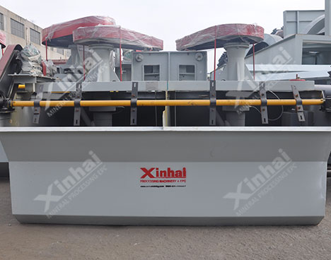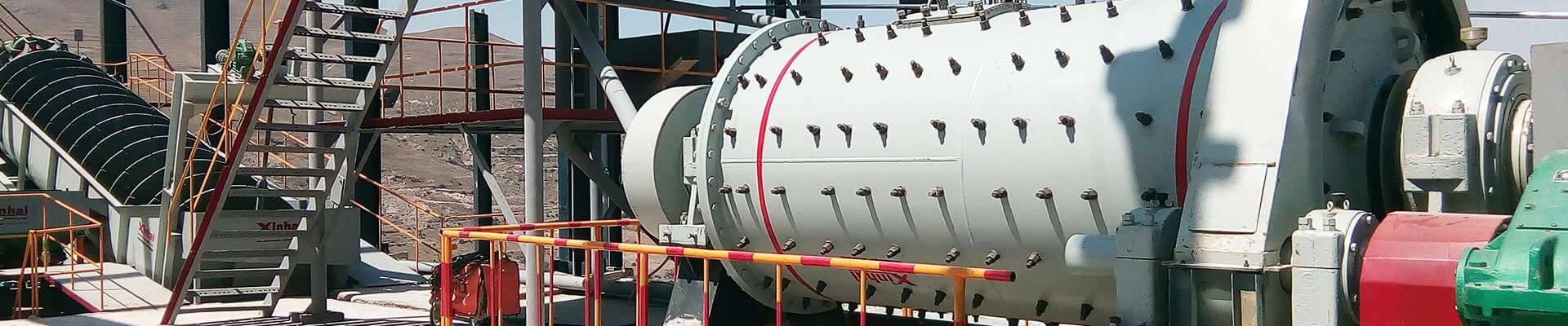
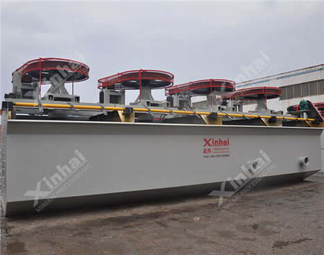
An inflatable flotation device that does not absorb slurry (refer to the design of the Outokumpu OK flotation machine in Finland). 【Processing capacity】: 0.2~38m³/min 【Scope of application】: KYF type air-filled mechanical stirring flotation machine is suitable for roughing and selection operations in large and medium-sized concentrators. Non-ferrous metals, ferrous metals and non-metallic minerals can be selected. The particle size range of selected materials is 0.3~0.01mm (-0.074mm grain grade content> 50%).
The impeller of kyf flotation machine is a conical impeller whose blades are inclined backward at an angle, with strong stirring ability and simple structure;
A hollow cylindrical air distributor is installed in the impeller cavity, the air is evenly dispersed, and the air slurry is well combined;
The impeller diameter is small, the peripheral speed is low, the power consumption is low, and the energy can be saved by 30-50%;
The ore particles are well suspended and the flotation index is high;
U-shaped trough is adopted, with less tailings deposition;
The wearing parts are lightly worn and have a long service life;
Mechanical stirring type, can not self-suction, can not self-suction slurry, the operation room needs to be arranged in steps;
It can be combined with KCF flotation machine to form a combined flotation unit as a direct flow tank.

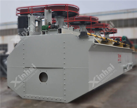
KYF air inflation floatation cell working principle: when the flotation cell is at work, the rotation of impeller makes the slurry all around via tank bottom absorbed from downside of impelle into inner-vanes of impeller, where low pressure air produced by the blower goes into via hollow shaft and the air distributor of impeller chamber at the same time. After fully mixture of the slurry and air among vanes, they are pushed out in inclined upward direction from upper half of the impeller around, and go into the tank via steady f\ow and orientation by the stator. Air bubbles rise to the foam stability area, and after concentration process, the froths overflow from the overflow dam into the froth tank. Another part of the slurry flows to ward the lower part of impeller, then through the impeller agitation, they are mixed together to form mineral laden bubbles again, and the rest of the slurry will flow to the next tank to become tailings eventually.
| Model | Effective Volume (m3) | Capacity (m3/min) | Impeller Diameter (mm) | Impeller Revolution (r/min) | Air Pressure of Blower (kPa) | Max. Air Inflation Volume (m3/m2.min) | Motor Power for Agitation (kW) | Motor Power for Scraper (kW) | Weight (kg) |
| KYF-1 | 1 | 0.2~1 | 340 | 281 | ≥ 12.6 | 2 | 4 | 0.75 | 903 |
| KYF-2 | 2 | 0.4~2 | 410 | 247 | ≥ 14.7 | 2 | 5.5 | 1.1 | 1419 |
| KYF-3 | 3 | 0.6~3 | 480 | 219 | ≥ 19.8 | 2 | 7.5 | 1.5 | 1885 |
| KYF-4 | 4 | 1.2~4 | 550 | 200 | ≥ 19.8 | 2 | 11 | 1.5 | 2206 |
| KYF-8 | 8 | 3.0~8 | 630 | 175 | ≥ 21.6 | 2 | 15 | 1.5 | 3984 |
| KYF-10 | 10 | 4.0~10 | 630 | 192 | ≥ 21.6 | 2 | 22 | 1.5 | 4406 |
| KYF-16 | 16 | 4.0~16 | 740 | 160 | ≥ 25.5 | 2 | 30 | 1.5 | 5900 |
| KYF-24 | 24 | 4.0~24 | 800 | 150 | ≥ 30.4 | 2 | 30 | 1.5 | 7500 |
| KYF-38 | 38 | 10.0~38 | 880 | 139 | ≥ 34.3 | 2 | 45 | 1.5 | 10300 |

A concentrator in South Africa wanted to purchase a flotation machine for fluorite ore processing. The requirements were: large capacity, high efficiency and energy saving. After communicating with many equipment manufacturers, the ideal model could not be selected. For personnel exchanges, KYF flotation machine was selected. The innovative point of the machine lies in the unique impeller-stator structure and slot form. In this application, the fluid state in the tank is reasonable, the slurry is in a good suspension state, the foam layer is stable, and the operation is normal and stable. The grade of the ore after sorting has generally improved, meeting the needs of the plant.
 +86 13811510145